Chapter 32Ear-EEG and Multimodal Sensing at the Ear
The ear holds an earpiece steady, sits a few centimetres from the temporal lobe, and is a place people already wear technology all day.
- explain what ear-EEG records, and why its signals are smaller than scalp EEG;
- choose electrode sites and references in and around the ear;
- budget the noise of an ear-EEG channel, and see why the contact matters more than the amplifier;
- add photoplethysmography, pulse oximetry, temperature and motion at the ear;
- partition an ear-worn system between the earpiece, the rest of the device and a phone, on one clock.
What input noise, electrode contact and electrode placement does an ear-worn front-end need to record EEG that is worth recording?
Clinical EEG uses a cap of electrodes spread over the scalp, held with gel, applied by a technician, and worn for an hour. That suits a hospital, not daily life. Ear-EEG places the electrodes in and around the ear, where an earpiece holds them in place without a cap [53]. It cannot see the whole brain, but it records the activity that reaches the temporal regions well: sleep rhythms, alpha, auditory responses and, for some patients, seizures [54, 57]. The same earpiece can also measure the pulse, blood oxygen, temperature and head motion. This chapter is about what that means for the front-end of Parts II and III.
32.1What the ear can record
EEG potentials are the far field of synchronised cortical currents (Chapter 2). What a pair of electrodes records depends on how much of that field lies between them: two electrodes close together, both in one ear, see only a small part of it. Ear-EEG measured within one ear therefore has amplitudes several times smaller than scalp EEG between distant electrodes, while measurements between the two ears, or between the ear and the mastoid or the side of the head, are larger [54]. Studies comparing ear-EEG with nearby scalp electrodes find that it follows the temporal scalp channels closely, that auditory evoked responses are recorded with useful signal-to-noise ratio, and that sleep stages can be scored from it [57, 54]. Electrodes printed on a flexible sheet around the ear extend the same idea to larger distances [56].
32.2Electrode sites and references
An earpiece offers a handful of sites: the ear canal, the bowl of the outer ear (the concha and the smaller cymba above it), the skin behind the ear and over the mastoid bone. Their trade-offs:
- Canal electrodes sit closest to the temporal lobe and are held firmly by the earpiece, but the canal is small, moist, and its shape differs between people; the earpiece must be sized or shaped to each ear for a stable contact.
- Concha and cymba electrodes have more area and less variation, and they add distance from the canal electrodes.
- Behind-the-ear and mastoid sites give the longest distances within one side of the head and a convenient place for the right-leg-drive or reference electrode (Chapter 12).
The reference shapes what is recorded. A reference in the same ear makes every channel a short, low-amplitude bipolar pair. A reference in the other ear, or on the far mastoid, gives much larger signals, at the cost of a wire, or a radio and a shared clock, between the two sides of the head. Recording each electrode against a common reference and forming the pairs digitally keeps every option open.
32.3Dry contacts and the noise budget
Gel and an ear are a poor combination for daily use, so ear-EEG is usually recorded with dry electrodes: sintered Ag/AgCl, metals coated with iridium oxide or similar, or conductive polymers, shaped to the ear [55]. Their impedance is higher and less stable than a gel electrode’s, which brings back every concern of Chapter 3 and Chapter 10: input impedance, offset range, the noise of the contact itself and its motion artefacts (Chapter 31).
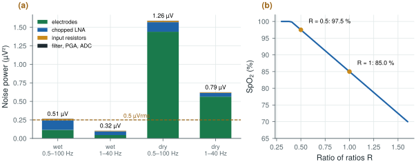
Start from the channel budget of Chapter 29, all referred to the input over 0.5–100 Hz: electrodes 0.34 µVrms (wet) or 1.20 µVrms (dry), chopped LNA 0.36 µVrms, input resistors 0.13 µVrms, the rest 0.05 µVrms. The total is 0.51 µVrms wet and 1.26 µVrms dry (Figure 32.1a). For ear-EEG, whose rhythms are a few microvolts, aim for about 0.5 µVrms. Narrowing the band to the 1–40 Hz that sleep and alpha need scales each white term by \(\sqrt{39/99.5} = 0.63\): 0.32 µVrms wet, 0.79 µVrms dry. With wet contacts the amplifier and the electrodes share the budget; with dry contacts the electrodes take 90 % of the noise power, and no amount of LNA current reaches 0.5 µVrms. The contact, not the chip, decides.
figsrc/ch32_figs.py.The demo below puts the budget and the referencing together for alpha, the rhythm most ear-EEG studies start with. It starts with dry contacts in one ear and the alpha band alone; try wet gel, a reference behind the ear, and the full EEG band.
32.4More than EEG at the ear
An earpiece reaches more than the brain [58].
- Photoplethysmography (PPG). An LED shines into well-perfused skin and a photodiode measures the light that comes back; each heartbeat changes the blood volume and so the signal by a fraction of a per cent. The ear canal and the concha are well perfused and less affected by cold than a finger. PPG gives the heart rate and its variability (Chapter 24) without an ECG electrode.
- Pulse oximetry. With two wavelengths, red and infrared, the ratio of ratios \(R = (\mathrm{AC}/\mathrm{DC})_\mathrm{red} / (\mathrm{AC}/\mathrm{DC})_\mathrm{IR}\) maps to the blood’s oxygen saturation through an empirical calibration (Figure 32.1b). The front-end is a transimpedance amplifier and a converter for the photodiode, and pulsed LED drivers whose current, not the amplifier, dominates the power.
- Temperature, from a thermistor or an infrared sensor looking into the canal.
- Motion, from an accelerometer and gyroscope: activity, head position, and the reference signals for artefact cancellation of Chapter 31. Jaw movement and speech also reach the ear, as artefacts in the EEG and as signals in their own right.
- An ECG lead, between electrodes on the two sides of the head or neck: far smaller than a chest lead, but enough for the R peak.
Each modality brings its own front-end, and the EEG’s microvolts must coexist with LED current pulses of tens of milliamperes a few millimetres away: separate supplies and grounds, and LED pulses timed away from the EEG’s sampling instants, keep the two apart.
32.5Partitioning an ear-worn system
The physics suggests a partition. Digitise at the ear: the microvolt signals travel millimetres, not along a cable, and only digital lines leave the earpiece; the front-end chip of this tutorial, at microwatts per channel, is small and cool enough to sit there. Compute and transmit away from the ear, in a part of the device with room for a battery and an antenna, or on a phone; Chapter 27 sizes the radio link. Clock everything from one source: EEG, impedance, PPG, motion and any sound the device plays must share one time base, or the artefact references of Chapter 31 and the closed loops of Chapter 33 fall apart. Two earpieces need either a wire that carries the clock or a radio protocol with common anchor points.
The power budget is set by what draws current continuously. A low-power EEG front-end costs microwatts to a few milliwatts depending on the chip; PPG LEDs cost hundreds of microwatts to milliwatts, depending on how often they flash; a BLE link costs tenths of a milliwatt to milliwatts depending on what it carries. Features computed on the device, short LED pulses and long radio intervals are the levers.
Ear-EEG needs about a third of the input noise that scalp EEG needs, and with dry contacts the electrodes, not the amplifier, set it: invest in the contact, its area and its fit, and narrow the band to what the application uses. Record against a common reference and form pairs digitally, digitise in the earpiece, and run every sensor from one clock.
Comparing ear-EEG with scalp EEG by amplitude alone. Short within-ear pairs record smaller signals by geometry, not because the electrodes are poor; judge an ear-EEG system by its signal-to-noise ratio for a defined task (an alpha band, an evoked response, sleep stages), with the same references and bands on both sides of the comparison.
Change the electrode noise in figsrc/ch32_figs.py to model a better dry contact, and find the electrode noise at which the 1–40 Hz budget reaches 0.5 µVrms. Then use biosig.eeg() with its alpha amplitude scaled down by four to stand for a within-ear pair, and see how much of it survives that noise.
Read with this chapter. Looney et al. [53], Mikkelsen et al. [54], Kidmose et al. [57], Kappel et al. [55], Debener et al. [56], Allen [58].
- Ear-EEG follows the temporal scalp channels; within one ear its amplitudes are several times smaller, and references in the other ear or behind it give larger signals.
- Sites: canal, concha and cymba, behind the ear and mastoid; record against a common reference and form pairs digitally.
- Over 1–40 Hz the channel noise is 0.32 µVrms with wet contacts and 0.79 µVrms with dry ones: with dry contacts the electrodes dominate.
- The ear also gives PPG, SpO2 (a ratio of ratios, calibrated empirically), temperature, motion and an ECG lead.
- Digitise at the ear, compute and transmit away from it, and clock every sensor from one source.