Chapter 3Electrodes and the Body as a Circuit
The electrode is the first component of the circuit: before the amplifier sees anything, it adds an offset of hundreds of millivolts, a frequency-dependent impedance and its own noise.
- compare wet Ag/AgCl, dry and implanted electrodes;
- explain half-cell potentials and the DC offset they leave between two electrodes;
- model the electrode–skin interface with the Randles circuit;
- compute the thermal noise of an electrode;
- derive the input impedance the amplifier needs.
What input impedance, offset tolerance and noise floor does the electrode force on the amplifier?
3.1Electrode types
In the body, current is carried by ions; in the wire, by electrons. An electrode is where one becomes the other, through a chemical reaction at its surface. How easily that reaction runs decides almost everything about the electrode as a circuit element.
- Wet Ag/AgCl electrodes are the clinical standard. A silver disc coated with silver chloride sits in a chloride gel, and the reaction \(\mathrm{Ag} + \mathrm{Cl^-} \rightleftharpoons \mathrm{AgCl} + e^-\) runs freely in both directions. Such an electrode is called non-polarisable: current passes with little change in its voltage, so its potential is stable and its noise is low. The gel wets the outer layer of the skin and lowers its impedance.
- Dry electrodes (metal, conductive polymer, or spiked contacts) touch the skin directly, which suits long-term wearables and EEG headsets. Without gel the contact impedance is ten to a hundred times higher, it varies between electrodes, and it is more sensitive to motion [19].
- Implanted microelectrodes are tens of micrometres across and sit in the tissue, where there is no skin. Their tiny area makes them strongly capacitive, with impedances of hundreds of kilohms at 1 kHz.
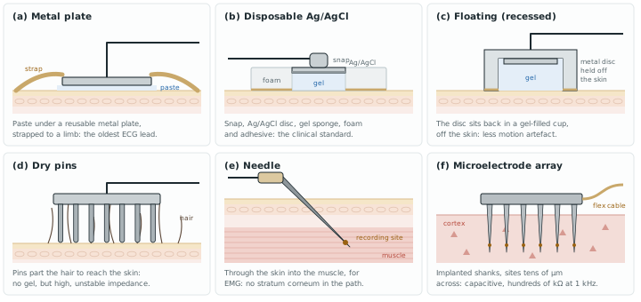
Beyond these three families, the shape of an electrode follows where it goes [7]; Figure 3.1 sketches six of them:
- On the skin. Metal plates strapped to the limbs (the oldest ECG electrode); metal discs held with tape; floating electrodes, recessed in a gel-filled cup so that the metal never touches the skin, which keeps the double layer still and cuts motion artefact; suction cups for short chest recordings; flexible electrodes of carbon-filled silicone or printed conductors for curved or fragile skin, as on infants; dry-contact pins that reach through hair for EEG; and small coated-metal electrodes in a soft earpiece for ear-EEG.
- Through or under the skin. Needle electrodes for EMG and short EEG sessions; helical electrodes that screw a few millimetres into the scalp, for fetal ECG during labour; subcutaneous implants for long-term EEG.
- In the tissue. Metal microelectrodes and microfabricated arrays in one, two or three dimensions for extracellular spikes, and electrolyte-filled glass micropipettes for recording inside a cell.
3.2Half-cell potential and DC offset
Every electrode in an electrolyte develops a half-cell potential \(E_\mathrm{hc}\), the voltage across its surface reaction. For Ag/AgCl it is about +0.222 V against the standard hydrogen electrode. Two identical electrodes would cancel, but in practice they never are identical: the skin under each one, the gel, the chloride concentration and the pressure all differ. The skin itself adds a potential of its own, \(E_\mathrm{se}\), across its outer layer, which changes when the skin is stretched.
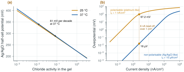
The half-cell potential is set by chemistry and temperature, through the Nernst equation. For Ag/AgCl, \(E_\mathrm{hc} = E^0 - (RT/F)\ln a_\mathrm{Cl^-}\): the electrode responds to the chloride activity of the gel, not to the silver. At 37 °C, \(RT/F\) = 26.7 mV, so a tenfold change in chloride shifts the potential by 61 mV (Figure 3.2a). Two electrodes on gels of different chloride concentration therefore start tens of millivolts apart, and drift as sweat changes the gel.
Once current flows, the electrode moves away from its half-cell potential by an overpotential with three parts [7]: an ohmic drop in the electrolyte, a concentration term as the ions near the surface are used up, and an activation term, the extra voltage the reaction needs to run at that rate. How large it gets separates two ideals. A perfectly polarisable electrode passes no charge across its surface and behaves as a capacitor: noble metals such as platinum and gold, and stainless steel, come close. A perfectly non-polarisable electrode passes charge freely and behaves as a resistor: Ag/AgCl comes close (Figure 3.2b). The DC lead-off currents of Chapter 12 and every stimulation current pass through this interface, which is why their size matters.
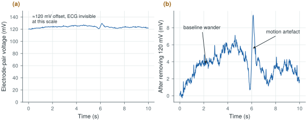
The difference between two electrodes is a DC offset of tens to hundreds of millivolts, much larger than any biopotential and slowly drifting. The ECG standards require an electrocardiograph to work with ±300 mV of offset at its input [42]. Figure 3.3 shows what that looks like: an offset of about 120 mV on which the 1 mV ECG is invisible, plus baseline wander and a motion artefact.
Tolerate ±300 mV of electrode DC offset at every input without saturating. With a 1.2 V supply and a front-end gain of 50 or more, this offset must be removed before or inside the first stage (Chapter 10).
3.3The electrode–skin model
Figure 3.4 cuts through a gelled electrode on the skin and joins each layer to an element of the standard equivalent circuit, which Figure 3.5 (top) draws on its own. At the metal–gel interface, the half-cell potential \(E_\mathrm{hc}\) is in series with the Randles network [38]: a charge-transfer resistance \(R_\mathrm{d}\), through which the reaction passes current, in parallel with the double-layer capacitance \(C_\mathrm{d}\), the thin layer of charge that forms at any electrode surface. The gel adds a series resistance \(R_\mathrm{s}\). The outer layer of the skin, the epidermis, adds its own potential \(E_\mathrm{se}\) and a resistance \(R_\mathrm{e}\) in parallel with a capacitance \(C_\mathrm{e}\). The dermis and the tissue below are almost purely resistive, \(R_\mathrm{u}\).
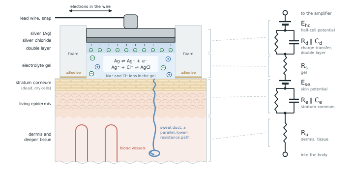
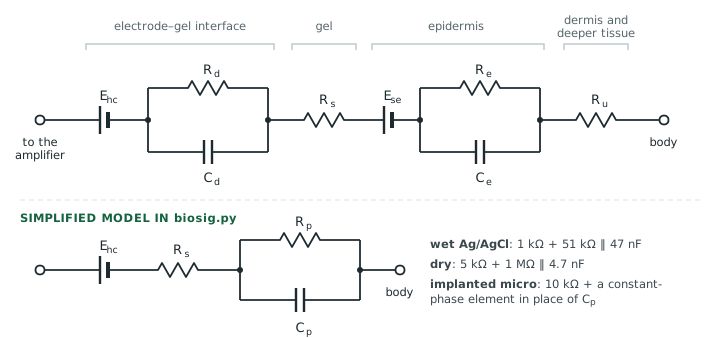
biosig.py, one series resistance and one parallel RC (or a constant-phase element for an implanted microelectrode), with the values of the three electrode types.For design, the two parallel networks merge into one, giving the simplified model at the bottom of the figure. Its impedance is
Below the corner \(f_\mathrm{p}\) the electrode is resistive, \(R_\mathrm{s} + R_\mathrm{p}\); above it, the capacitor takes over and the impedance falls towards \(R_\mathrm{s}\). For the wet electrode the model uses 1 kΩ in series with 51 kΩ‖47 nF, the network the ECG standards use to represent one poor electrode contact; for a dry electrode, 5 kΩ in series with 1 MΩ‖4.7 nF. An implanted microelectrode is better described by a constant-phase element, \(Z = 1/(Q(j\omega)^n)\) with \(n \approx 0.85\), whose phase stays near \(-n \times 90^\circ \approx -76^\circ\) at all frequencies.
Wet: \(f_\mathrm{p} = 1/(2\pi \cdot 51\ \text{kΩ} \cdot 47\ \text{nF}) = 66\) Hz. At 0.67 Hz, \(\lvert Z_\mathrm{e}\rvert \approx 1 + 51 = 52\) kΩ; at 50 Hz, where the capacitor starts to help, 41.5 kΩ.
Dry: \(f_\mathrm{p} = 1/(2\pi \cdot 1\ \text{MΩ} \cdot 4.7\ \text{nF}) = 34\) Hz. At 0.67 Hz, \(\lvert Z_\mathrm{e}\rvert \approx 1.0\) MΩ; at 50 Hz, 564 kΩ.
Across the ExG band the dry electrode is about twenty times worse, and its impedance changes more with frequency (Figure 3.6).
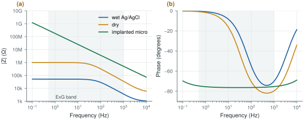
biosig.z_electrode(), with the ExG band shaded. Wet and dry electrodes are resistive at low frequency and capacitive above their corner; the implanted microelectrode is capacitive everywhere.Most of the skin’s resistance sits in its outermost layer, the stratum corneum, a few tens of micrometres of dead, dry cells. Its impedance per unit area is of the order of hundreds of kilohm-square-centimetres at 1 Hz, falling to hundreds of ohm-square-centimetres at 1 MHz as its capacitance takes over [7]. That is why gel matters, and why clinical practice lightly abrades the skin before applying an electrode: removing part of the stratum corneum lowers the impedance by an order of magnitude and also reduces the potential that appears when the skin is stretched.
3.4Electrode noise
Any resistance at temperature \(T\) produces thermal noise, and the electrode is no exception: its noise comes from the real part of its impedance. The noise voltage of one electrode over a band from \(f_1\) to \(f_2\) is
A wet electrode at 310 K is about 52 kΩ at low frequency, so its noise density is \(\sqrt{4kT \cdot 52\ \text{kΩ}} \approx 30\) nV/√Hz. Over the 99.5 Hz of the EEG band that gives about 0.30 µVrms. The exact integral is a little lower, 0.24 µVrms, because \(\mathrm{Re}\{Z_\mathrm{e}\}\) falls above 66 Hz (Figure 3.7b).
A channel has two electrodes, whose noise adds in power: \(\sqrt{2} \times 0.24 = 0.34\) µVrms. That leaves \(\sqrt{1.5^2 - 0.34^2} = 1.46\) µVrms for the amplifier, almost the whole budget.
A dry electrode gives 0.85 µVrms each, or 1.20 µVrms for the pair. Only \(\sqrt{1.5^2 - 1.2^2} = 0.9\) µVrms is left for the amplifier, and that is before any excess noise.
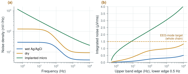
Thermal noise is only a lower bound. Real electrodes, dry ones above all, show excess noise well above \(4kT\,\mathrm{Re}\{Z\}\), with a \(1/f\)-like spectrum that comes from the chemistry at the interface and from skin movement. Measure your electrodes before you spend the noise budget.
3.5Motion artefacts and impedance mismatch
When the skin stretches or the electrode shifts, the skin potential \(E_\mathrm{se}\) and the charge in the double layer change, and the electrode voltage jumps by millivolts (Figure 3.3b). These motion artefacts fall in the same band as the ECG, so filtering cannot remove them; good skin preparation, firm contact and a stable gel reduce them, and the front-end must at least not saturate when they happen.
The two electrodes of a pair also never have the same impedance. This impedance mismatch matters more than the impedance itself, because it turns the common-mode interference on the body into a differential signal that the amplifier cannot reject (Chapter 4). The 51 kΩ‖47 nF network in one lead is how the standards create this mismatch on purpose when they test an ECG.
Two practical rules follow from the chemistry [7]. Every part of an electrode that the electrolyte can reach, the contact, its plating and any solder or clip, must be the same metal; two metals in one electrolyte form a galvanic cell, with its own offset and noise. And the lead wire must not pull on the electrode: a light, flexible lead taped in a loop near the electrode means that a tug moves the loop, not the double layer.
3.6Input impedance
The electrode impedance and the amplifier’s input impedance \(Z_\mathrm{in}\) form a divider, so only part of the electrode voltage reaches the amplifier.
The ECG standards turn this into a test [46, 42]: a 620 kΩ resistor in parallel with 4.7 nF is placed in series with one input, with ±300 mV of DC offset, and the signal at 0.67 Hz and 40 Hz must not drop by more than 20 %.
At 0.67 Hz the 4.7 nF is about 50 MΩ, so the test source is essentially 620 kΩ. A 20 % drop means \(Z_\mathrm{in}/(Z_\mathrm{s} + Z_\mathrm{in}) \geq 0.8\), or \(Z_\mathrm{in} \geq 4 Z_\mathrm{s}\):
\[Z_\mathrm{in} \geq 4 \times 620\ \text{kΩ} = 2.48\ \text{MΩ}\]At 40 Hz the source is 500 kΩ and the requirement 2.0 MΩ. The low-frequency case sets the familiar rule: at least 2.5 MΩ per input.
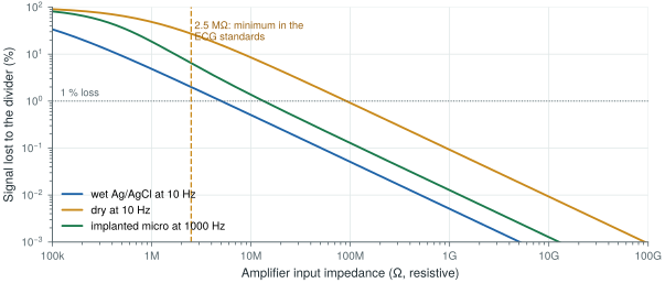
2.5 MΩ is the floor the standards set for wet electrodes. Open-BioAFE aims much higher: 100 MΩ or more for dry electrodes, and a common-mode input impedance that keeps mains interference below the noise, which Chapter 4 derives (above 1 GΩ at 50 Hz on its own, about 12 MΩ with the right-leg drive of Chapter 12). A plain MOS gate is easily that high; what pulls the input impedance down is the chopper’s input capacitors, which Chapter 10 has to boost back up.
Lab 2 builds these electrode models with biosig.z_electrode(), computes their noise with thermal_noise_rms(), and then adds the body and the mains of Chapter 4 to find the CMRR and input impedance the amplifier needs.
Read with this chapter. Webster [7] for electrode chemistry and models, Chi, Jung and Cauwenberghs [19] for dry and non-contact electrodes.
- Ag/AgCl with gel is non-polarisable: stable potential, low impedance (about 50 kΩ in the model) and low noise. Dry electrodes are about twenty times higher in impedance; implanted microelectrodes are capacitive.
- Two electrodes never match: expect up to ±300 mV of DC offset, plus drift and motion artefacts in the signal band.
- The simplified model, \(R_\mathrm{s} + R_\mathrm{p} \parallel C_\mathrm{p}\), is resistive below \(f_\mathrm{p}\) and capacitive above it.
- Thermal noise of the pair: about 0.34 µVrms (wet) or 1.2 µVrms (dry) in 0.5–100 Hz, against a 1.5 µVrms target. Excess noise comes on top.
- The standards’ input-impedance test gives at least 2.5 MΩ per input; dry electrodes and interference push the target to 100 MΩ and above.