Chapter 31Signal Quality and Motion Artefacts
On a moving person the hardest question is not how small a signal the chip can resolve, but whether the sample it just produced can be trusted.
- explain the mechanisms by which motion turns into voltage at the electrodes;
- measure contact quality during a recording, with impedance tracking and with other indicators the chip already has;
- cancel an artefact adaptively from reference signals with the NLMS algorithm, and choose its references, length and step size;
- build a signal-quality index that travels with the data;
- budget the hardware and computation that all of this costs.
Which references, measured by the same chip on the same clock, let a wearable remove motion artefacts it cannot filter, and tell the user when it cannot?
Everything in Parts I to V assumed a still subject. A wearable is worn by someone who walks, talks, chews and turns their head, and every movement disturbs the electrodes. The resulting motion artefacts are often larger than the signal and, worse, they fall in the same band: from a fraction of a hertz to tens of hertz, exactly where the ECG, EEG and EMG live. No filter can separate what shares a band. This chapter shows how to recognise motion artefacts, how to measure the electrode contact while recording, and how to subtract the artefact using signals that are correlated with it but not with the biosignal.
31.1How motion becomes voltage
Four mechanisms dominate [7].
- The interface itself. Moving an electrode relative to its gel disturbs the double layer of Chapter 3 and so its half-cell potential. Floating electrodes, gel, and Ag/AgCl’s non-polarisable surface reduce it.
- The skin. Stretching the skin changes the potential across its outer layer by millivolts. Light abrasion of the skin reduces it.
- Currents through a changing impedance. Any current through the electrode turns its impedance change into a voltage. The DC lead-off current of Chapter 12 is one such current; the common-mode current from the mains is another, through the divider \(\Delta Z / Z_\mathrm{cm}\) of Chapter 4, whose imbalance \(\Delta Z\) now moves with every step.
- The cables. Flexing leads generates triboelectric charge, and moving leads change their capacitance to the body and to the mains. Short, light, shielded leads, or digitising close to the electrodes, reduce it.
The DC lead-off detector of Chapter 12 passes 6 nA through each electrode. A dry electrode whose impedance swings by 20 kΩ as the wearer walks then produces \(6\ \text{nA} \times 20\ \text{k}\Omega = 120\) µV of artefact, at the walking rhythm: six times a typical EEG. An AC impedance measurement at tens of kilohertz (Chapter 28) moves its own artefact out of band, and turning the DC lead-off current off while recording removes this term altogether.
31.2Measuring contact quality while recording
The contact cannot be judged once at the start: it changes as the gel dries, as the wearer sweats, and with every movement. A wearable needs indicators that it can read continuously, on the same clock as the signal.
- Electrode impedance, by the out-of-band tone and IQ demodulation of Chapter 28. Its magnitude says how good the contact is, its phase how much of it is capacitive, its imbalance between electrodes how much mains will convert to differential mode, and its rate of change how much the contact is moving. A tone injected through the right-leg drive reaches every electrode at once, so one source can track all channels.
- The DC servo’s output (Chapter 10), which follows the electrode offset: a step means the interface was disturbed.
- Mains power in the signal, a free measure of the impedance imbalance: the 50 Hz line rises when one contact degrades.
- Saturation and clipping counters in the converter path.
- Motion itself, from an accelerometer next to the electrodes.
Each indicator costs little. The impedance channel costs a few microwatts (Chapter 29); the rest are numbers the chip already computes.
31.3Adaptive cancellation
When a measured signal \(x\) is correlated with the artefact but not with the biosignal, the artefact can be predicted from \(x\) and subtracted. This is adaptive noise cancelling [51]. The recorded signal is \(d = s + a\), biosignal plus artefact. An adaptive FIR filter with weights \(\mathbf{w}\) turns the last \(L\) samples of each reference into an estimate \(y = \mathbf{w}^\mathsf{T}\mathbf{x}\) of the artefact, and the output is \(e = d - y\). Because \(s\) is uncorrelated with \(\mathbf{x}\), minimising the power of \(e\) can only remove the part of \(d\) that the references explain: the artefact.
\(\mathbf{x}\) holds the last \(L\) samples of every reference, \(0 < \mu < 2\) is the step size and \(\delta\) regularises the division.
The normalised LMS (NLMS) update makes the step independent of the reference’s level [52]. Three choices set its performance:
- The step size \(\mu\) trades tracking speed against misadjustment: the biosignal itself jitters the weights, and that jitter appears as added noise. Values from 0.001 to 0.05 are typical.
- The length \(L\) must cover the delay and the shape of the path from reference to artefact: a few samples for an impedance trace, tens for an accelerometer whose effect lags through the mechanics of the skin.
- The regularisation \(\delta\) matters more than it looks. Motion references are bursty, nearly zero between movements; dividing by a tiny \(\mathbf{x}^\mathsf{T}\mathbf{x}\) then turns the EEG into huge weight jumps that ruin the next movement. Set \(\delta\) of the order of the references’ typical power.
References. An accelerometer measures the cause of the artefact, not its electrical path: it sees the movement, but not how each electrode responds to it. The electrode impedance measures the interface itself, but not the parts of the artefact that bypass it, such as cable motion. The two are complementary. Figure 31.1 cancels a synthetic artefact, built from an impedance-driven part (a lead-off current through the moving contact) and a part that follows acceleration directly, with each reference and with both.
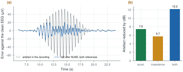
figsrc/ch31_figs.py.Three conditions make it work on real data. The references must be sampled on the same clock as the signal, or their delay changes and the filter chases it; this is one more argument for measuring impedance on the recording chip. The references must not contain the biosignal: an impedance trace demodulated out of band is clean, but an accelerometer on the head picks up the ballistocardiogram, the tiny motion of each heartbeat, and can cancel part of a cardiac signal. And the filter must be stopped from adapting when there is no movement, or reset after a large one, or it drifts.
Try it below on the same kind of synthetic recording. Change the references, the step size and the number of taps, slide how much of the artefact comes through the impedance, and switch the regularisation off to see the filter fail between movements.
31.4A signal-quality index
Cancellation reduces artefacts; it does not abolish them. A wearable should therefore say, for each window of data, how far it can be trusted. A signal-quality index combines the indicators of section 31.2 into a number or a few classes: good, usable with care, unusable. The simplest version is a set of thresholds (impedance above a limit, servo step, clipping, mains power, acceleration above a limit); a better one is a classifier trained on recordings labelled by experts, with the indicators as its features.
The index belongs with the data, sample by sample or window by window, in the same packets (Chapter 27). Downstream, it gates what the algorithms may conclude: a seizure detector (Chapter 25) should not alarm on a window flagged unusable, a sleep scorer should mark it, and an analysis of many nights can weight each window by its quality instead of throwing whole nights away.
31.5What it costs the chip
The hardware is mostly already there. The impedance channel of Chapter 28 adds of the order of 5 µW when running; an accelerometer adds tens of microwatts; the servo outputs, clipping counters and mains-power estimate are by-products. The computation is small: eight channels, two references of eight taps and 500 S/s need \(8 \times 16 \times 500 \times 2 = 128\,000\) multiply-accumulates per second for the filter and as many for the update, well within a microcontroller and within reach of a small on-chip datapath. What matters more is time: impedance, motion and signal must share one sample clock, and the sample counter must travel with every packet.
Plan for motion from the start. Keep currents through the electrodes small or out of band, measure the electrode impedance continuously on the recording chip and its clock, add a motion sensor, and send a quality flag with every window. Cancel what the references explain with a regularised NLMS filter, and flag what they do not.
Judging an artefact remover by how clean the output looks. A filter that removes “too much” removes signal: if the reference contains the biosignal, as a head-mounted accelerometer contains the heartbeat, the canceller subtracts it. Test on recordings with a known clean reference, or on synthetic artefacts added to clean data, and report what was removed from the signal as well as from the artefact.
Run figsrc/ch31_figs.py, then change the artefact model in scene(): make it depend only on acceleration, or only on impedance, and watch which reference wins. Set δ back to a tiny number and see the filter blow up between movements.
Read with this chapter. Widrow et al. [51], Haykin [52], Webster [7] (motion artefacts).
- Motion artefacts come from the electrode interface, the skin, currents through a changing impedance and the cables; they share the signal’s band, so filters cannot remove them.
- A 6 nA lead-off current through a 20 kΩ impedance swing is 120 µV of artefact: keep electrode currents small or out of band.
- Measure contact quality continuously: impedance by IQ demodulation, servo steps, mains power, clipping and acceleration.
- NLMS cancels what correlated references explain; regularise it against bursty references, and keep references free of the biosignal and on the signal’s clock.
- In the synthetic example, the accelerometer and the impedance remove 7.5 and 5.7 dB alone and 12.2 dB together.
- Send a signal-quality index with the data and let it gate what downstream algorithms conclude.