Chapter 12Common-Mode Control and Electrode Monitoring
The third electrode is not a reference: it is the output of a feedback loop that pins the body to the amplifier’s common mode.
- design a right-leg drive (driven-right-leg) loop and analyse its stability;
- relate RLD loop gain to the residual common-mode and differential interference;
- implement common-mode feedback for the multichannel front-end;
- detect lead-off with DC and AC methods;
- protect the inputs against ESD and defibrillation pulses in SG13G2;
- filter RF before the first transistor without losing CMRR;
- drive cable shields and guards so the leads do not load the inputs.
How much right-leg-drive gain and which protection network let the Open-BioAFE channel pass the ECG CMRR test with margin?
Chapter 4 left an open question. With the standards’ imbalance network, the ECG CMRR test would need a common-mode input impedance of more than a gigaohm if the whole test voltage reached the electrodes. The chopped front-end of Chapter 10 reaches about 200 MΩ. This chapter closes the gap by controlling the body’s common mode, and then looks after everything else that touches the inputs: lead-off detection, protection, RF filtering and shielding.
12.1The right-leg drive loop
A passive ground electrode lets the mains displacement current set the body’s common-mode voltage, 9 mV in Worked Example 4.1. A right-leg drive (RLD) instead senses the average of the input common-mode voltages, compares it with the amplifier’s mid-supply, and drives the third electrode with the inverted, amplified error. The loop forces the body towards mid-supply, and the common mode left at the electrodes is reduced by one plus the loop gain [20] (Figure 12.1):
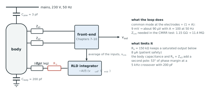
Every requirement on the common-mode input impedance falls by the same factor.
The test applies 10 Vrms of common mode at 50 Hz with a 40.7 kΩ imbalance in one lead, and allows 1 mVpp at the output referred to the input (Chapter 4). Without an RLD that needs \(Z_\mathrm{cm} \ge 1.15\) GΩ. With a loop gain of 100 at 50 Hz it needs only 11.4 MΩ.
With the amplifier’s 100 dB of intrinsic CMRR included (Figure 12.2a): the chopped but unboosted front-end (6.25 MΩ) leaves 1.8 mVpp and fails; the boosted front-end (200 MΩ) leaves 0.06 mVpp, 24 dB inside the limit. A loop gain of 10 would leave 0.55 mVpp with the boosted front-end, a pass with only 5 dB of margin.
Stability. The RLD loop contains the patient. The amplifier, usually an integrator for high gain at 50 Hz, drives the body’s capacitance to ground (about 200 pF, varying from person to person) through the RL electrode and a series resistor \(R_\mathrm{o}\). That forms a second pole at \(1/[2\pi C_\mathrm{body}(R_\mathrm{o} + Z_\mathrm{e})]\). A loop gain of 100 at 50 Hz means an integrator crossover at 5 kHz, and the phase margin depends on where the second pole falls (Figure 12.2b).
Safety. A large transient, a lead falling off or a defibrillation pulse drives the RLD amplifier to its rail. The body then sees the rail through \(R_\mathrm{o}\) alone, so \(R_\mathrm{o}\) must keep that current below the 10 µA patient-current limit for DC (Chapter 4): at 1.2 V, \(R_\mathrm{o} \ge 120\) kΩ. A larger \(R_\mathrm{o}\) is safer but moves the second pole down. With 390 kΩ the phase margin at a 5 kHz crossover is 35°; with 1 MΩ, 23°.
\(R_\mathrm{o} = 150\) kΩ limits the saturated current to 8 µA and gives a phase margin of 53° at a 5 kHz crossover with 200 pF of body capacitance; 45° with 300 pF and 67° with 100 pF. A small lead network across the integrator, or a crossover at 2 kHz (loop gain 40, margin 70°), buys more margin if the body capacitance turns out larger.
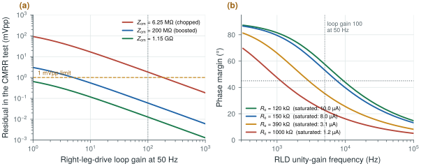
figsrc/ch12_figs.py.12.2Common-mode feedback
Every fully differential stage needs a common-mode feedback (CMFB) loop that holds its output common mode at mid-supply, independent of the input common mode and of the differential signal. In Open-BioAFE each of the eight channels has one in its LNA and its PGA. Switched-capacitor CMFB suits the chopped LNA: it shares the chopper clock, has no static current, and its capacitors set the common-mode level without loading the differential signal. The CMFB loop must be faster than the differential path it serves, or the output common mode drifts during large differential swings. A shared bias network, distributed to the channels as currents rather than voltages, keeps the channels matched.
The RLD sense point is the average of all channels’ input common modes, taken through high-value resistors or capacitors at the inputs. With eight channels the average is less sensitive to one electrode losing contact. A lead-off flag (section 12.3) removes that electrode from the average.
12.3Lead-off detection
A detached or drying electrode must be flagged, not digitised as signal. Two methods are used.
DC lead-off feeds a small current, a few nanoamperes, into each input through a high-impedance source, and returns it through the RL electrode. With a good contact the resulting voltage is small: 6 nA through a 1 MΩ dry electrode is 6 mV, well within the DC servo range. With a broken contact the input drifts to the rail within milliseconds, and a comparator or the servo integrator’s output (Chapter 10) flags it. The current is far below the 10 µA DC limit, but it does polarise the electrode slightly.
AC lead-off injects a small current above the signal band and measures the voltage it produces. That is a measurement of the electrode impedance, not only a yes-or-no flag. It must stay within the frequency-dependent patient-current limits (Chapter 4), and it must not intermodulate with the signal. Open-BioAFE extends it into continuous impedance tracking with I/Q demodulation in Chapter 28.
Figure 12.3 compares the two. The DC method needs only two current sources per channel and a detector the chip already has; the AC method reuses the whole channel and returns a number instead of a flag.
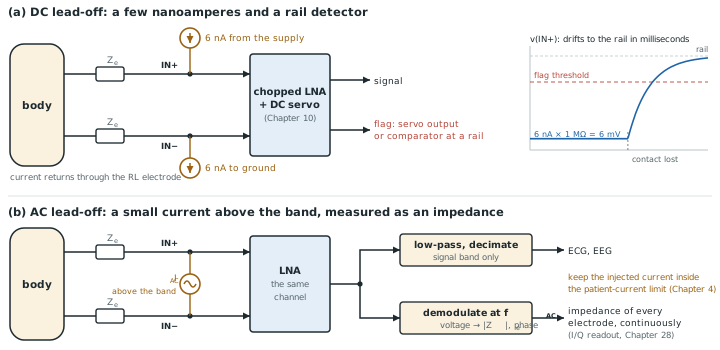
figsrc/ch12_leadoff_svg.py.12.4Input protection, ESD and RF filtering
Every input pin connects the chip to a patient and to whoever handles the cable. It needs protection against electrostatic discharge, typically 2 kV human-body-model at the pins and more at the connector, and, for ECG, against defibrillation: up to 5 kV across the electrodes for a few milliseconds (Chapter 4).
No on-chip structure survives a defibrillator directly. The defibrillation energy is absorbed off chip, by high-voltage series resistors of tens of kilohms and, in many designs, gas-discharge or TVS clamps in the cable or connector. On chip, the IHP PDK’s ESD diodes (the sg13g2_esd library) clamp each pin to the supplies, with a modest series resistor between pad and input device. Each element costs something:
- Series resistance adds thermal noise. 5 kΩ per input adds \(\sqrt{2 \cdot 4kT \cdot 5\ \text{kΩ} \cdot 99.5\ \text{Hz}} = 0.13\) µVrms to the pair over the EEG band, and 10 kΩ adds 0.18 µVrms. Against a chopped amplifier at 0.36 µVrms (Chapter 10) that is a real cost, so keep the on-chip resistor small and let the off-chip network do the heavy work.
- ESD diodes leak. Their reverse current, picoamperes at room temperature and much more at 85 °C, flows through the electrode impedance as an offset and adds shot noise, and in an unchopped LNA it upsets the pseudo-resistor’s bias (Chapter 8).
- Capacitance loads the input. The diodes and pad add the picofarads that cap the boosted input impedance in Chapter 10.
RF filtering. Phones, Wi-Fi and electrosurgery units put RF on the leads, and the input transistors rectify it into a baseband offset or envelope (Chapter 4), as described by Ott [48]. A series resistor and a capacitor to ground at each input form a low-pass filter that removes RF before the first transistor. A mismatch between the two inputs’ RC time constants turns common mode into differential mode by \(2\pi fR\,\Delta C\), so the filter costs CMRR (Figure 7.3b). With 5 kΩ and 10 pF (a 3 MHz corner) and 1 pF of mismatch, the CMRR limit at 50 Hz is 116 dB, which is harmless. A capacitor directly across the two inputs, larger than the two capacitors to ground, filters differential RF without depending on their matching.
12.5Shielding, guarding and active electrodes
Cable shields stop capacitive pickup on the leads, but they must be connected correctly. Tie each shield to the reference at one end only; connected at both ends, a shield carries ground-loop current and injects it into the very lead it protects [47]. A grounded shield also loads the input. Its capacitance to the inner wire, about 100 pF per metre, is part of \(Z_\mathrm{cm}\): about 30 MΩ at 50 Hz for a one-metre lead (Chapter 4). With the RLD of section 12.1 that is enough for the CMRR test, but it is far below what a dry electrode wants.
Driving the shield at the potential of the wire inside it removes that load, because no current flows through a capacitance with no voltage across it. A buffer per channel, following that channel’s input, drives its shield; or, more cheaply, one buffer drives all shields at the common-mode voltage, which removes the common-mode load. On the board, a guard trace around each high-impedance input, driven in the same way, stops leakage across the board surface from reaching the input. On chip, the same idea applies to the input routing: surround it with a ring driven at the input’s common mode rather than at ground.
Active electrodes take this to its end point. A unity-gain buffer at the electrode itself drives the cable from a low impedance, so the cable’s capacitance and pickup no longer matter. Dry and non-contact electrodes, with source impedances of megaohms to gigaohms, depend on it [19]. The price is electronics, power and a supply wire at every electrode, so Open-BioAFE treats active electrodes as a system option and provides a shield-drive output on chip.
Magnetic pickup is not stopped by any of these. The two leads and the body close a loop, and a 50 Hz magnetic field induces a voltage in it that is already differential. Routing the leads together, or twisting them, keeps the loop small (Chapter 4).
A right-leg drive with a loop gain of about 100 at 50 Hz divides every common-mode problem by a hundred, which turns the gigaohm requirement of Chapter 4 into about 11 MΩ and lets the boosted front-end pass the CMRR test with 24 dB of margin. Choose its series resistor from safety first (at least 120 kΩ at 1.2 V) and then check the phase margin over the full range of body capacitance. Detect lead-off with nanoampere DC currents, and save the AC method for impedance tracking. Keep the on-chip series resistance small, because it adds noise, and the input RC filters matched. Drive the shields rather than grounding them.
RLD: integrating amplifier with a 5 kHz crossover (loop gain 100 at 50 Hz), sense point the average of the active channels’ inputs, series resistor 150 kΩ (8 µA when saturated, 53° phase margin at 200 pF). CMRR test residual 0.06 mVpp with the boosted inputs (24 dB margin). DC lead-off at a few nanoamperes per input; AC impedance tracking in Chapter 28. On-chip input resistor ≤ 5 kΩ with SG13G2 ESD diodes; defibrillation protection off chip. Common-mode shield-drive output.
Testing the RLD loop with a single body capacitance. People differ, a patient lying on a bed differs from one standing, and the cable adds its own capacitance. A loop that is stable with 200 pF may ring with 400 pF and inject a tone into every channel. Sweep the body capacitance from about 50 to 500 pF and check that the loop is stable and well damped at both ends.
Lab 2 already adds a behavioural right-leg drive to the body model of Chapter 4. Extend it with figsrc/ch12_figs.py: add the integrator, the safety resistor and the body capacitance, and reproduce Figure 12.2.
Read with this chapter. Winter and Webster [20], Huhta and Webster [21], Webster [7], Rich [47] (shielding and guarding), Ott [48] (RF rectification and filtering).
- A right-leg drive divides the electrodes’ common mode by \(1 + A\); with \(A = 100\) the CMRR test needs 11.4 MΩ of \(Z_\mathrm{cm}\) instead of 1.15 GΩ, and the boosted front-end passes with 24 dB of margin.
- The RLD loop includes the body’s capacitance; its safety resistor (≥ 120 kΩ at 1.2 V for 10 µA) sets a second pole, and 150 kΩ gives 53° of margin at a 5 kHz crossover.
- Lead-off: nanoampere DC currents for a flag, AC injection for an impedance measurement.
- On-chip series resistance adds noise (0.13 µVrms for 5 kΩ per input); defibrillation energy belongs off chip; input RC filters must match.
- Ground shields at one end, or better drive them; active electrodes remove cable loading entirely; twist the leads against magnetic pickup.