Chapter 4Interference, Safety and Standards
The patient sits in the mains field, so the front-end has to reject volts of common-mode interference while it amplifies microvolts, and it must never hurt the patient.
- model how the mains couples to the body;
- compute how electrode impedance imbalance turns common-mode interference into a differential signal;
- read the CMRR test of the ECG standards and derive the CMRR it implies;
- summarise patient leakage-current limits, isolation, defibrillation and ESD;
- state the heating limits for implants.
How much CMRR and common-mode input impedance does Open-BioAFE need, and which safety limits bound the design?
Whatever reaches the amplifier besides the wanted signal comes in three kinds [7]. Transmitted noise is part of the measured quantity itself: other biosignals (EMG on an ECG, the ECG on an EEG) and motion. Interference couples in from outside, from the mains and from radio sources; it is the subject of this chapter. Inherent noise is generated by the electrodes and the electronics (Chapters 3 and 6). Filtering helps only against what lies outside the signal’s band; inside it, each kind must be fought at its source.
4.1Mains coupling
A person in a room is a conductor between two capacitors: a few picofarads to the mains wiring in the walls and ceiling, \(C_\mathrm{pow}\), and a few hundred picofarads to the floor and to earth, \(C_\mathrm{body}\) [21]. The mains drives a small displacement current \(i_\mathrm{d}\) through this path (Figure 4.1). Because the current is the same at every electrode, it raises the whole body to a common-mode voltage \(V_\mathrm{cm}\) that the amplifier must ignore.
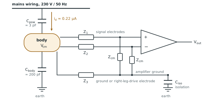
With 230 V at 50 Hz and \(C_\mathrm{pow} = 3\) pF, \(i_\mathrm{d} = 2\pi \cdot 50 \cdot 3\ \text{pF} \cdot 230\ \text{V} \approx 0.22\) µA.
If nothing connects the body to the amplifier, the two capacitors divide the mains: \(V_\mathrm{cm} = 230 \times 3/(3 + 200) \approx\) 3.4 V.
With a ground electrode of 51 kΩ‖47 nF, which is 40.7 kΩ at 50 Hz, the current flows out through it instead, and \(V_\mathrm{cm} \approx 0.22\ \text{µA} \times 41.5\ \text{kΩ} \approx\) 9 mV (the 41.5 kΩ includes the electrode’s 1 kΩ series resistance).
Nine millivolts is still six thousand times the 1.5 µVrms noise target. The amplifier’s job is to reject it, and the next section shows what limits how well it can.
The path through the body is the largest, but three others reach the inputs directly, and CMRR does nothing against them:
- Magnetic pickup. The two leads and the body close a loop, and the mains magnetic field induces a voltage in it that is already differential. A 1 µT field at 50 Hz, common near mains equipment, through a 100 cm² loop induces \(2\pi \cdot 50 \cdot 1\ \text{µT} \cdot 0.01\ \text{m}^2 \approx 3\) µV, twice the noise target. Twisting the leads together shrinks the loop; a thin shield does not help, because a 50 Hz magnetic field passes through it.
- Capacitive coupling to the leads. Stray capacitance from the mains to each unshielded lead drives current into its electrode impedance, and the two leads never pick up the same amount. A grounded shield stops this, but its capacitance to the inner wire, around 100 pF per metre, is now part of \(Z_\mathrm{cm}\): about 30 MΩ at 50 Hz for a one-metre lead, far below the 1 GΩ goal, unless the shield is driven.
- Radio frequencies. Phones, Wi-Fi and electrosurgery units put RF on the leads. It lies far above the ExG band, but the input transistors are nonlinear and rectify it into a baseband offset or a demodulated envelope, so it has to be filtered before the first transistor.
Chapter 12 covers shields, guards and RF filtering; Rich [47] gives the classic rules.
4.2From common mode to differential mode
Each signal input sees a divider: its electrode impedance in series, the amplifier’s common-mode input impedance \(Z_\mathrm{cm}\) to ground. If the two electrodes were identical, both inputs would see the same fraction of \(V_\mathrm{cm}\) and the difference would be zero. They are not, and an imbalance \(\Delta Z\) turns part of \(V_\mathrm{cm}\) into a differential signal that no amplifier can tell from the ECG [16]. For \(Z_\mathrm{cm} \gg Z_\mathrm{e}\):
The second form shows that the electrodes and the input impedance behave like a second CMRR in parallel with the amplifier’s own: the worse of the two wins.
Take \(V_\mathrm{cm} = 9\) mV from Worked Example 4.1 and the standards’ imbalance network in one lead, \(\Delta Z = 40.7\) kΩ at 50 Hz. The mains that appears on the signal is:
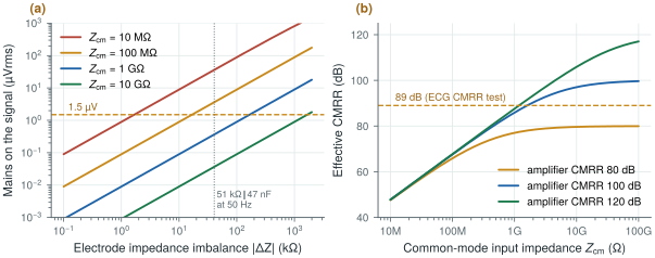
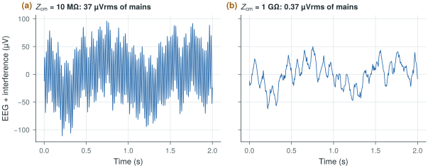
| \(Z_\mathrm{cm}\) | 10 MΩ | 100 MΩ | 1 GΩ | 10 GΩ |
|---|---|---|---|---|
| \(V_\mathrm{dm}\) | 36.6 µVrms | 3.7 µVrms | 0.37 µVrms | 0.037 µVrms |
Only from about 1 GΩ does the interference fall well below the 1.5 µVrms noise target (Figure 4.2a). At 50 Hz, 1 GΩ is the impedance of just 3.2 pF: every picofarad of pad, wire and switch capacitance at the input counts.
The other way to win is to make \(V_\mathrm{cm}\) smaller. A right-leg drive senses the average of the input voltages and drives the opposite through the ground electrode, so that the body’s common mode is reduced by one plus the loop gain [20]. A loop gain of 100 takes the 9 mV of Worked Example 4.1 down to about 90 µV. Chapter 12 designs it, including its stability with the electrode impedance in the loop.
4.3The CMRR test of the ECG standards
The standards for electrocardiographs and ECG monitors test common-mode rejection in a way that includes the electrodes [45, 42, 43]. A mains-frequency source drives all the leads together through a capacitive network, equivalent to about 10 Vrms of common mode behind 200 pF. One lead has the 51 kΩ‖47 nF imbalance network in series, with 300 mV of DC offset, and the indicated signal must stay below 1 mV peak-to-peak, or 10 mm on a 10 mm/mV trace.
10 Vrms is \(2\sqrt{2} \times 10 = 28.3\) Vpp. Reducing it to below 1 mVpp needs
\[\mathrm{CMRR} \geq 20\log_{10}\frac{28.3\ \text{V}}{1\ \text{mV}} = 89.0\ \text{dB}.\]If the whole 10 V reached the electrodes, the imbalance term alone would need \(Z_\mathrm{cm} \geq 40.7\ \text{kΩ} \times 28\,300 = 1.15\) GΩ at 50 Hz (no more than 2.76 pF), or 1.07 GΩ at 60 Hz (2.48 pF). This is a worst-case bound: in the test, the source impedance and the amplifier’s own ground connection reduce the common mode that actually reaches the inputs.
Open-BioAFE targets 90 dB, a little above the 89 dB of the test. From the effective-CMRR equation, with a 100 dB amplifier:
\[\frac{\Delta Z}{Z_\mathrm{cm}} \leq 10^{-90/20} - 10^{-100/20} = 2.16\times10^{-5} \ \Rightarrow\ Z_\mathrm{cm} \geq \frac{40.7\ \text{kΩ}}{2.16\times10^{-5}} \approx 1.9\ \text{GΩ}.\]With a 120 dB amplifier the requirement eases only to 1.3 GΩ. The input impedance, not the amplifier’s CMRR, is the hard part (Figure 4.2b).
Effective CMRR above 90 dB at 50 and 60 Hz with the standards’ imbalance network. This needs an amplifier CMRR of 100 dB or more and a common-mode input impedance of about 2 GΩ at 50 Hz if nothing reduces the body’s common mode. The right-leg drive of Chapter 12 divides that requirement by its loop gain, to about 12 MΩ, and Chapter 29 confirms the split.
Datasheet CMRR is measured with the inputs shorted together, with no imbalance network. A part that claims 120 dB can deliver well under 90 dB with real electrodes if its common-mode input impedance is low. Typical electrocardiographs measure in the mid-90s of dB under the standard test. The ambulatory standard [44] uses only 2.8 Vrms, which implies about 78 dB: make sure you know which test a number refers to.
Try the budget below. It starts at the design point this chapter and Chapter 12 arrive at: the standards’ 40.7 kΩ imbalance, 200 MΩ of boosted input impedance, 100 dB of CMRR and a right-leg drive with a loop gain of 100. Then switch the right-leg drive off, or lower \(Z_\mathrm{cm}\), and watch which term takes over.
4.4Patient safety
A front-end connects conductors to a person, so it must limit the current that can flow through them. IEC 60601-1 [41] classifies the parts that touch the patient, the applied parts: type B (body), type BF (body, floating: the patient connection is isolated, as for skin ECG) and type CF (cardiac, floating: suitable for direct contact with the heart, the strictest). It then limits the patient leakage current and the patient auxiliary current (current that flows between electrodes by design, such as lead-off detection or bioimpedance excitation). In summary, for a.c. in normal condition, 100 µA for types B and BF and 10 µA for type CF; under a single fault, 500 µA and 50 µA; and 10 µA of d.c. The body is less sensitive at higher frequencies, so above 1 kHz the limits rise in proportion to frequency, up to 100 kHz, but never above 10 mA (Figure 4.4). These are summaries for teaching: always work from the edition of the standard that applies to your device.
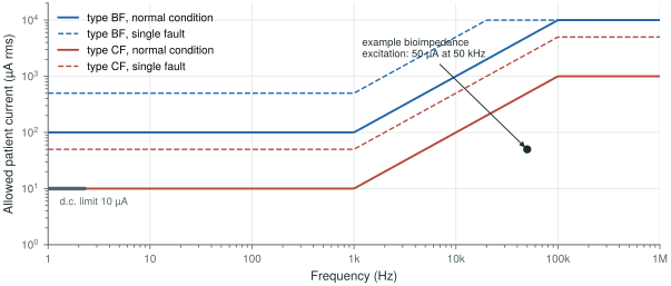
biosig.patient_current_limit(), and the 10 µA d.c. limit. A bioimpedance excitation of 50 µA at 50 kHz sits a factor of ten below the CF limit at that frequency.Lead-off detection injects a small d.c. current into each electrode and watches for the voltage to rise when an electrode comes off (Chapter 12). Currents of a few nanoamperes are enough, three orders of magnitude below the 10 µA d.c. limit, but the circuit must stay below that limit even if a transistor fails short.
Bioimpedance for respiration (Chapter 28) drives an a.c. current between electrodes. At 50 kHz the CF limit is \(10\ \text{µA} \times 50 = 500\) µA, so a 50 µA excitation has a tenfold margin. At 1 kHz the same current would exceed the CF limit five times.
4.5Isolation, defibrillation and ESD
Isolation. The patient connection must be isolated from the mains and from earth. A battery-powered wearable is isolated by construction, its only path to earth being a small capacitance \(C_\mathrm{iso}\); a mains-powered instrument needs an isolation barrier in its power supply and data path.
Defibrillation. An ECG input may be connected to a patient when a defibrillator fires, putting several kilovolts across the electrodes. The front-end must survive this and recover quickly enough to show the ECG again within seconds. Protection uses series resistors and clamps outside the chip.
ESD. System-level tests apply ±8 kV contact and ±15 kV air discharges to the device. On-chip ESD protection, designed for the human-body model during handling, cannot absorb that on its own; external protection takes the energy, and the on-chip diodes handle what is left (Chapter 12).
Every protection resistor in series with an input adds thermal noise. A 10 kΩ resistor at room temperature contributes \(\sqrt{4kT \cdot 10\ \text{kΩ}} \approx 13\) nV/√Hz, or 0.13 µVrms over 0.5–100 Hz; 100 kΩ contributes 0.41 µVrms, and there is one per input. Protection and noise have to be budgeted together, which Chapter 29 does.
4.6Implants
For an implant, the limit is heat. Tissue is damaged by sustained temperature rises of a few degrees, so implant designers aim to keep the rise near 1 °C [39]. That translates into power-density limits of the order of tens of milliwatts per square centimetre, which depend on the implant’s position and size. Eight Open-BioAFE channels at 10 µW each on a 2 mm × 2 mm die is \(80\ \text{µW} / 0.04\ \text{cm}^2 = 2\) mW/cm², far below; a thousand-channel implant at the same power per channel, 10 mW on a square centimetre, is not far from the limit, which is why high-channel-count implants push power per channel even lower.
Lab 2 builds the circuit of Figure 4.1 with biosig.body_cm_voltage() and cm_to_dm(), injects 10 Vrms of mains common mode, sweeps the amplifier CMRR, the common-mode input impedance and the electrode imbalance, and adds a behavioural right-leg drive. It prints the CMRR the design needs, which should match Worked Examples 4.3 and 4.4.
Read with this chapter. Huhta and Webster [21] for the classic analysis of mains interference, Pallàs-Areny and Webster [16, 33] for CMRR with real sources, Winter and Webster [20] for the driven right leg, and the MEDTEQ notes [45, 46] for how the ECG standards’ tests work in practice.
- The mains couples about 0.22 µA into the body. A floating body sits at volts; with a ground electrode, at about 9 mV of common mode.
- Electrode imbalance turns common mode into differential mode: \(V_\mathrm{dm} \approx V_\mathrm{cm}\,\Delta Z / Z_\mathrm{cm}\). With the standards’ 40.7 kΩ imbalance, \(Z_\mathrm{cm}\) must reach the gigaohm range, which at 50 Hz means only a few picofarads.
- The ECG CMRR test implies 89 dB; Open-BioAFE targets 90 dB, which with a 100 dB amplifier needs about 1.9 GΩ of common-mode input impedance.
- A right-leg drive reduces the common mode by one plus its loop gain.
- Patient currents are limited to 10 µA (CF) or 100 µA (BF) a.c. in normal condition and 10 µA d.c., rising above 1 kHz; inputs must also survive defibrillation and system-level ESD, and implants must keep tissue heating near 1 °C.