Chapter 11Filters, PGAs and Anti-Aliasing
Between the LNA and the ADC the signal needs more gain, a defined bandwidth and protection from aliasing, at corner frequencies from a fraction of a hertz to a few kilohertz.
- design Gm-C and switched-capacitor filters with sub-hertz to kilohertz corners;
- design a programmable-gain amplifier for the three Open-BioAFE modes;
- choose the anti-aliasing filter order from the ADC oversampling ratio;
- explain why mains notch filters belong in the digital domain.
How much filtering and gain does each mode need before the SAR and the ΔΣ ADC, and where should each filter live?
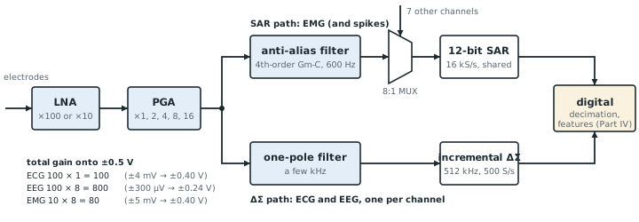
The LNA of Chapters 8–10 delivers a gain of 10 or 100, a chopper ripple at 4 kHz, and a band that reaches tens of kilohertz. The converters of Part III want a signal that fills their range, a band no wider than they can sample without aliasing, and no ripple. This chapter sets the gain and the filtering between the two (Figure 11.1).
11.1Very-low-frequency filters on chip
A first-order low-pass filter made from a transconductor \(g_\mathrm{m}\) and a capacitor \(C\) has its corner at
At biosignal frequencies the transconductances are tiny.
With \(C = 10\) pF, a 100 Hz corner needs \(g_\mathrm{m} = 2\pi \times 100 \times 10\ \text{pF} = 6.3\) nS. At \(g_\mathrm{m}/I_\mathrm{D} = 25\) V⁻¹ that is a bias current of 0.25 nA; a 1 kHz corner needs 2.5 nA (Figure 11.2a). A 0.5 Hz corner would need 1.3 pA, the size of the junction leakage of the devices themselves, so sub-hertz Gm-C filters are impractical. Open-BioAFE sets its sub-hertz corner with the DC servo loop of Chapter 10 instead.
Small transconductances come with two further problems. Linear range: a weak-inversion differential pair is linear over only tens of millivolts, so the transconductors need source degeneration or input attenuation to handle signals of hundreds of millivolts. Noise: the integrated output noise of a Gm-C filter is about \(\xi\,kT/C\), where the excess factor \(\xi\) counts the noisy transistors and is typically 2–4. On 10 pF, \(\sqrt{kT/C} = 20\) µVrms; with \(\xi = 4\) it is 41 µVrms. Referred to the electrodes through a gain of 100, that is 0.41 µVrms, a large share of the budget. Through a gain of 1000 it is 0.04 µVrms. Filters therefore come after the gain.
A switched-capacitor filter replaces the transconductance with a capacitor \(C_1\) switched at \(f_\mathrm{s}\), and its corner is set by a capacitor ratio and a clock, both precise. Clocked at the 4 kHz chopper frequency, a 100 Hz corner needs only \(C_2/C_1 = 6.4\). The price is sampling: the filter aliases what lies above \(f_\mathrm{s}/2\), so it needs a continuous-time pre-filter, and its switches add \(kT/C_1\) noise at each sample.
11.2Programmable gain
The converters want their full range used. Take a converter input range of ±0.5 V differential. The total gain from the electrodes should map each mode’s largest signal, plus some headroom for artefacts, onto that range (Chapter 2).
Table 11.1. Gain plan for the three modes. LNA gain from Chapter 8; the PGA is a capacitive amplifier with gains 1, 2, 4, 8 and 16.
| Mode | Largest signal | LNA gain | PGA gain | Total | Signal at the converter |
|---|---|---|---|---|---|
| ECG | ±4 mV | 100 (40 dB) | 1 | 100 | ±0.40 V |
| EEG | ±300 µV | 100 (40 dB) | 8 | 800 | ±0.24 V, 2× artefact headroom |
| EMG | ±5 mV | 10 (20 dB) | 8 | 80 | ±0.40 V |
| Spikes (optional) | ±500 µV | 100 (40 dB) | 8 | 800 | ±0.40 V |
The PGA is a second capacitively coupled stage, chopped or not, with switchable input capacitors. Its noise matters little: it is divided by the LNA’s gain of 10–100 when referred to the input. Placing it before the low-pass filter keeps the filter’s \(kT/C\) noise small in the same way.
11.3Anti-aliasing versus oversampling
Chapter 13 showed that the anti-alias filter is set by the interferers above the band, and that a faster converter relaxes it. The two Open-BioAFE converters sit at opposite ends of that trade.
The SAR in EMG mode samples at 2 kS/s for a 500 Hz band. Anything between 1.5 and 2.5 kHz folds into the band, and surface EMG still carries about 0.1 mV there. To push it below the EMG-band noise floor of 3.3 µVrms (Chapter 13) takes \(20\log_{10}(0.1\ \text{mV}/3.3\ \text{µV}) = 30\) dB at 1.5 kHz. A Butterworth filter at 600 Hz gives 16 dB at second order and 32 dB at fourth order (Figure 11.2b), so the EMG path gets a fourth-order Gm-C filter, with bias currents of a few nanoamperes.
The chopper ripple sits at 4 kHz, twice the SAR’s sample rate. Because the two clocks are locked together, the ripple aliases exactly to DC, where it adds to the offset rather than appearing as a tone, and the fourth-order filter attenuates it by 66 dB first. This is the reason for the synchronous clocks of Chapter 9.
The incremental ΔΣ in ECG/EEG mode clocks its loop at 512 kHz (Chapter 19). Nothing folds into the band until hundreds of kilohertz, where the LNA’s own roll-off already removes it, so one pole at a few kilohertz is enough. The 4 kHz ripple passes the analog path and is handled digitally. With an output rate of 500 S/s, 4 kHz is the eighth multiple of the rate, so with synchronous clocks it aliases to DC, an offset that the high-pass removes, and the incremental converter’s decimation filter attenuates it by about 28 dB on the way (Chapter 20).
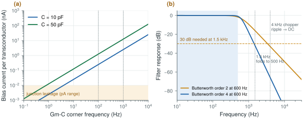
figsrc/ch11_figs.py.Try the trade-off below. It starts with the SAR path’s choice: 2 kS/s, a fourth-order Butterworth at 600 Hz, and an interferer at 1.5 kHz, which folds back to 500 Hz attenuated by 32 dB.
11.4Mains notch filtering
It is tempting to add an analog 50 Hz notch before the converter. It is a bad idea. A notch deep enough to matter, 40 dB, must sit within a fraction of a percent of the mains frequency, and on-chip resistors and capacitors drift by more than that over temperature and process. The mains frequency itself wanders by up to a few tenths of a hertz. A notch also distorts the ECG: its phase response smears the QRS complex, and its narrow band rings after artefacts.
After the converter, a notch can track the mains frequency, adapt its depth to the interference actually present, remove the harmonics with a comb, and be switched off for analysis that needs an untouched signal. Chapter 23 designs it. The analog chain’s job is only to keep the mains interference small (CMRR, Chapter 7; right-leg drive, Chapter 12) and to keep its harmonics from aliasing.
Put the gain first and the filters after it, so their \(kT/C\) noise is divided by the gain. Expect nanoampere transconductors in kilohertz Gm-C filters and give up on Gm-C below a few hertz; let the servo loop set the sub-hertz corner. Fit the anti-alias filter to the converter: fourth order at 600 Hz for the 2 kS/s SAR, a single pole for the 512 kHz incremental ΔΣ. Lock the chopper clock to both converters, so its ripple aliases to DC, where the high-pass removes it. Leave the mains notch to the digital domain.
PGA: capacitive, gains 1–16 in powers of two, after the LNA (gain plan in Table 11.1). SAR path: fourth-order Gm-C Butterworth at 600 Hz (EMG mode; raised to about 7 kHz in spike mode), capacitors of 10 pF or more, nanoampere bias. ΔΣ path: one pole at a few kilohertz. All clocks derived from one source: chopper 4 kHz, SAR 2 kS/s, ΔΣ loop 512 kHz with 500 S/s output.
Forgetting that a switched-capacitor filter is itself a sampled system. Clocked at 4 kHz, it folds everything near 4, 8, 12 kHz… into its band, including the chopper ripple if the two clocks drift apart. Precede it with a continuous-time filter, and keep its clock locked to the chopper.
Using biosig.butter_atten_db() and biosig.alias_freq(), find the lowest filter order and highest corner that meet 30 dB at 1.5 kHz for the SAR at 2 kS/s; then repeat for spike mode at 25 kS/s with a 7 kHz band.
Read with this chapter. Razavi [13] (switched-capacitor circuits), Yazicioglu, Van Hoof and Puers [8].
- A 100 Hz Gm-C corner on 10 pF needs 6.3 nS, a quarter of a nanoampere; sub-hertz Gm-C corners are lost in leakage.
- A Gm-C filter’s noise is about \(\xi kT/C\) (41 µVrms on 10 pF), so it belongs after the gain.
- The PGA brings each mode to the converter range: total gain 100 (ECG), 800 (EEG), 80 (EMG).
- The 2 kS/s SAR needs a fourth-order filter at 600 Hz; the 512 kHz incremental ΔΣ needs one pole.
- Synchronous clocks turn the chopper ripple into a DC offset at both converters; the ΔΣ decimator also attenuates it by about 28 dB.
- Mains notches belong after the converter.