Chapter 1Why Biomedical ICs?
Every biomedical front-end starts from an application: how many channels, which signal, how much noise, and how long the battery has to last.
- name the main applications (wearable ECG patches, Holter monitors, EEG headsets, sEMG prosthetic control, neural implants and brain–computer interfaces) and what limits each one;
- explain why integration wins on channel count, power and size;
- draw the Open-BioAFE signal chain and say which chapter covers each block;
- read the Open-BioAFE specification sheet;
- estimate battery lifetime and data rate from a power and sampling budget.
What does each application demand in channels, noise, power and lifetime?
1.1Applications
A biopotential is a voltage that a living tissue produces: the heart, the brain, the muscles and single neurons all generate one. To record it you place electrodes on the skin, on the brain surface or inside the tissue, and amplify the tiny difference between them. Five families of products do this today, and each pulls the design in a different direction.
- Wearable ECG patches stick to the chest for days or weeks and look for arrhythmias. They have one to three channels, run from a coin cell or a small rechargeable battery, and must survive motion, sweat and electrodes that dry out over time.
- Holter monitors record several ECG leads for one or two days of normal life. Their constraint is the same as the patch, power and storage over a long recording, with more channels and a stricter clinical bandwidth.
- EEG headsets record the brain’s rhythms from the scalp. The signals are only tens of microvolts, so the input noise must be around one microvolt, and with dry electrodes the source impedance is high and unequal between channels.
- Surface EMG for prosthetic control reads muscle activity on the forearm to drive a prosthetic hand. EMG is large by comparison (up to a few millivolts) and wider in bandwidth, and the classifier that turns it into gestures needs low latency.
- Neural implants and brain–computer interfaces record spikes and local field potentials from electrodes in the cortex. They need many channels, each with a few microwatts and a fraction of a square millimetre, because every milliwatt heats the tissue around the implant.
Table 1.1. Five applications and what limits them. Typical values; individual products vary.
| Application | Channels | Signal and band | What limits the design |
|---|---|---|---|
| Wearable ECG patch | 1–3 | ECG, 0.5–40 Hz (monitoring) to 0.05–150 Hz (diagnostic) | Battery life on a small cell, motion artefacts, long-wear electrodes |
| Holter monitor | 3–12 leads | ECG over 24–48 h | Power and storage over the whole recording, lead-off detection |
| EEG headset | 8–64 | EEG, 0.5–100 Hz, a few to a few hundred µV | Input noise near 1 µVrms, high and unequal electrode impedance, CMRR |
| sEMG prosthetic control | 4–16 | EMG, 10–500 Hz, up to a few mV | Latency, motion and sweat, channel count on the forearm |
| Neural implant / BCI | tens to over a thousand | Spikes 300 Hz–7 kHz, LFP below 300 Hz | Power density and heating, area per channel, wireless data rate |
Read the last column as the answer to the design question of this chapter. Wearables are limited by energy, scalp EEG by noise and interference, EMG by dynamic range and latency, and implants by power density and area. The Open-BioAFE chip is a general-purpose front-end, so it aims at the hardest of each: EEG-grade noise, EMG-grade bandwidth, and microwatt power per channel.
1.2Why integrate
You can build an ECG amplifier from discrete parts: an instrumentation amplifier, a few op-amps for filtering, a converter and a microcontroller. Commercial multi-channel analog front-ends of this kind are of the order of 1 mW per channel. Integrated designs do better on three counts.
- Power. A front-end designed transistor by transistor spends its current only where the noise is set, in the input pair. Research front-ends reached a few tens of microwatts per channel two decades ago [15, 17], and the best designs today are well below that.
- Channel count and size. Eight channels with their converters fit in a few square millimetres. A neural implant with hundreds of channels is impossible any other way.
- Matching. Channels on one die match closely, so the common-mode rejection and the gain of each channel are predictable.
Integration has a price. MOS transistors have large \(1/f\) noise at the low frequencies where biopotentials live, so the front-end needs chopping (Chapter 9). The 1.2 V core supply leaves little room for the ±300 mV that electrodes add (Chapter 3), so the offset must be removed before the signal is amplified (Chapter 10). And every block has to be designed and verified, which is what this tutorial is about.
1.3The signal chain
Figure 1.1 shows the blocks of Open-BioAFE and the chapters that design each one. The electrodes and the body come first, and they are part of the circuit: they set the source impedance, the offset and much of the interference (Chapters 2–4). ESD protection and lead-off detection guard the pins. A chopper low-noise amplifier (LNA) with a DC servo loop amplifies the signal while rejecting the electrode offset. A programmable-gain amplifier (PGA) and an anti-alias filter fit the signal to the converter. One of two converters then digitises it: a 12-bit SAR for EMG and spikes, or a 16-bit incremental ΔΣ for ECG and EEG. A decimation filter and feature extraction reduce the data, and a serial interface sends it out. A right-leg drive senses the common-mode voltage and drives it back into the body to reduce mains interference.
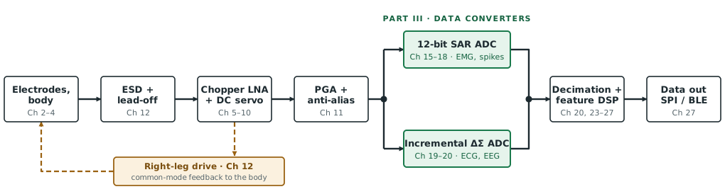
Why two converters? A DC-coupled ECG or EEG channel has to resolve microvolts on top of hundreds of millivolts of electrode offset, which needs about 16 bits at a few hundred samples per second. EMG and spikes need fewer bits at a much higher rate. A SAR converter is the most efficient choice for the second case, and an incremental ΔΣ for the first; Chapter 2 derives both numbers and Chapter 14 compares the architectures.
1.4The Open-BioAFE specification
Table 1.2 collects the targets. They are still to be confirmed by the budgets of Parts II and III, and each row names the chapters that set or meet it. The chip is built in IHP SG13G2, a 130 nm SiGe BiCMOS process with HBTs of roughly 350/450 GHz \(f_\mathrm{T}/f_\mathrm{max}\), 1.2 V core and 3.3 V I/O MOS devices, and MIM capacitors [1]. The HBTs have far lower \(1/f\) noise than the MOS devices, but their base current flows through the electrode impedance, a trade-off Chapter 5 weighs.
Table 1.2. The Open-BioAFE specification. Targets, and the chapters that set or meet each one.
| Parameter | Target | Chapters |
|---|---|---|
| Channels | 8, ECG, EEG or EMG selectable | 1 |
| Signal band | 0.5 Hz–1 kHz; spikes to 7 kHz optional | 2 |
| Input-referred noise | < 1.5 µVrms, 0.5–100 Hz (EEG mode) | 2, 3, 6 |
| CMRR | > 90 dB at 50/60 Hz | 4 |
| Electrode DC offset | ±300 mV tolerated | 3, 10 |
| Input impedance | ≥ 2.5 MΩ per input (≥ 100 MΩ with dry electrodes); common mode > 12 MΩ at 50 Hz with the right-leg drive (> 1.15 GΩ without) | 3, 4, 10, 12 |
| Converters | 12-bit SAR for EMG and spikes; 16-bit incremental ΔΣ for ECG and EEG | 13–20 |
| Front-end power | < 10 µW per channel | 6, 29 |
| Supply | 1.2 V | 5 |
| Process | IHP SG13G2 130 nm SiGe BiCMOS | 5, 30 |
| Bioimpedance | optional respiration channel | 28 |
| Data out | SPI | 27 |
Eight channels at less than 10 µW each: 80 µW for the whole analog front-end. Every later power budget is checked against this number.
1.5Battery life and data rate
A wearable’s lifetime is the battery energy divided by the average power of everything on it. For \(N\) channels at \(P_\mathrm{ch}\) each, plus the digital logic and the radio:
The battery energy is its capacity times its voltage. A CR2032 coin cell holds about 225 mAh at 3 V, which is \(0.225 \times 3 \times 3600 \approx 2430\) J.
Count only the analog front-end (\(P_\mathrm{dig} = P_\mathrm{radio} = 0\)).
- Open-BioAFE target, 8 × 10 µW = 80 µW: \(T = 2430 / 80\times10^{-6} = 3.0\times10^{7}\) s, about 352 days.
- Ten times the power, 8 × 100 µW = 800 µW: about 35 days.
- A discrete-class front-end, 8 × 1 mW = 8 mW: about 3.5 days.
Microwatt channels turn a patch you replace every few days into one that lasts a year.
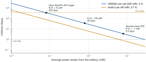
The coin-cell numbers count energy only. A CR2032 delivers its rated capacity at small, steady currents; a radio that draws several milliamps in bursts makes its voltage sag and wastes capacity. Real wearables add a small buffer capacitor or use a rechargeable cell for exactly this reason.
The radio is usually the largest consumer. The data rate is channels × sample rate × bits per sample.
- ECG/EEG mode: 8 channels × 500 S/s × 16 b = 64 kb/s.
- EMG mode: 8 × 2 kS/s × 12 b = 192 kb/s.
- Spike mode: 8 × 20 kS/s × 12 b = 1.92 Mb/s.
Take an illustrative low-power radio at about 10 nJ per bit. Streaming 64 kb/s costs \(64\times10^{3} \times 10\times10^{-9} = 0.64\) mW, eight times the 80 µW of the whole analog front-end, and spike mode would cost almost 20 mW.
Once the front-end reaches microwatts, the radio dominates the energy budget. Sending features instead of raw samples (a heart rate, a seizure flag, a gesture class) cuts the data rate by orders of magnitude, which is why Chapter 27 puts feature extraction on chip.
Read with this chapter. Webster [7] for the instruments and their clinical use, Sarpeshkar [12] for the energy argument behind low-power bioelectronics, Yazicioglu, Van Hoof and Puers [8] for integrated readout circuits.
- Each application is limited by something different: energy for wearables, noise and interference for EEG, dynamic range and latency for EMG, power density and area for implants.
- Integration buys power (microwatts instead of milliwatts per channel), channel count and matching, at the cost of designing around \(1/f\) noise, a 1.2 V supply and electrode offset.
- Open-BioAFE: 8 channels, < 1.5 µVrms of noise, > 90 dB CMRR, ±300 mV offset tolerance, a 12-bit SAR and a 16-bit incremental ΔΣ, and < 10 µW per channel in SG13G2.
- Battery lifetime is energy over average power: 80 µW gives about a year on a coin cell, 8 mW about three days.
- At microwatt front-end power the radio dominates, so the chip should send features, not raw samples.