Chapter 5Equalization Fundamentals
The channel is a low-pass filter. An equalizer is the filter we add so that channel and equalizer together look flat out to the Nyquist frequency.
In this chapter you will learn
Explain how loss at \(f_\mathrm{N}\) turns into inter-symbol interference and closes the REF eye.
State the zero-forcing idea and quantify why an ideal channel inverse amplifies noise.
Use a simple cable model to connect a loss in dB to the size of the main cursor.
Name the four places an equalizer can sit in a link, and what each one can and cannot fix.
Frame the partition question that Section 8.5 answers for Open-SERDES.
5.1Why equalize?
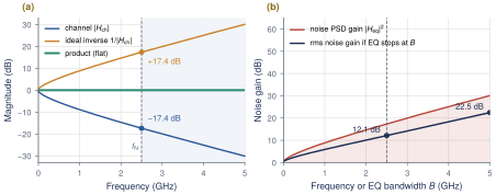
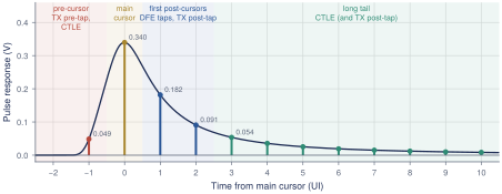
Section 3.7 showed that the REF channel loses 17.4 dB at \(f_\mathrm{N}=2.5\,\mathrm{GHz}\) but only 0.6 dB at DC. A single 1-UI pulse therefore comes out smeared. Its main cursor is only \(p_{0}=0.340\,\mathrm{V}\) instead of 1 V, and its energy leaks into the neighbouring bits: \(p_{1}=0.182\), \(p_{2}=0.091\) and a long tail after it, plus a small pre-cursor \(p_{-1}=0.049\) (Table 3.2). Summed over all bits, this inter-symbol interference (ISI) exceeds the main cursor, so the peak-distortion eye of Equation (4.2) is \(-0.161\) V. The eye is closed.
An equalizer is a filter \(H_\mathrm{eq}(f)\) placed somewhere in the link so that the cascade \(H_\mathrm{ch}(f)\,H_\mathrm{eq}(f)\) is flat, at least up to \(f_\mathrm{N}\) [22]. Flat to \(f_\mathrm{N}\) is enough. A pulse sampled once per UI is free of ISI when its spectrum, folded around multiples of \(1/T_\mathrm{b}\), adds up to a constant. A response that is flat to \(f_\mathrm{N}\) and rolls off smoothly above it comes close to meeting that condition. In the time domain, the same goal reads: make every cursor except \(p_{0}\) zero. Figure 5.1(a) shows the most direct way to do it, which is to build the exact inverse of the channel.
5.2The zero-forcing idea
A zero-forcing (ZF) equalizer chooses \(H_\mathrm{eq}=1/H_\mathrm{ch}\) over the band of interest, which forces all ISI to zero. It ignores noise, and that is its weakness. Thermal noise from the termination and from the first amplifier enters before the equalizer and is filtered by it. By the Wiener–Khinchin theorem, a noise process with power spectral density \(S_n(f)\) passing through \(H_\mathrm{eq}\) comes out with variance:
Key equation · Noise at the equalizer output
\[\sigma_\mathrm{out}^2=\int_0^{B}\lvert H_\mathrm{eq}(f)\rvert^2\,S_n(f)\,\mathrm{d}f \quad\xrightarrow{\;H_\mathrm{eq}=1/H_\mathrm{ch},\ S_n=N_0\;}\quad \sigma_\mathrm{out}^2=N_0B\cdot\underbrace{\frac{1}{B}\int_0^{B}\frac{\mathrm{d}f}{\lvert H_\mathrm{ch}(f)\rvert^2}}_{\text{noise enhancement}} \tag{5.1}\]
For REF the enhancement factor is 12.1 dB for \(B=f_\mathrm{N}\) (Figure 5.1b). The signal is not boosted by that much on average. The main cursor recovers, but the noise integrated over the whole band grows faster than the signal does. Extending the inverse to \(2f_\mathrm{N}\) costs another 10 dB of noise for almost no gain in eye opening. Practical equalizers are therefore partial inverses. They stop near \(f_\mathrm{N}\) and limit their peak boost, or, like the DFE of Chapter 8, they avoid linear filtering of the noise altogether.
A cable model
A model with a closed-form pulse helps build intuition. In a cable, dielectric loss dominates, and the transfer function is close to \(C(f)=\exp(-k_d\,l\,\lvert f\rvert)\), with \(l\) the length and \(k_d\) a loss coefficient. Write \(a=k_dl\). The inverse Fourier transform is a Lorentzian, \[c(t)=\int_{-\infty}^{\infty}e^{-a\lvert f\rvert}e^{j2\pi ft}\,\mathrm{d}f=2\int_0^\infty e^{-af}\cos(2\pi ft)\,\mathrm{d}f=\frac{2a}{a^2+4\pi^2t^2}. \tag{5.2}\] Convolving with a pulse of height \(V_0\) on \(0\le t\le T_\mathrm{b}\), and using the antiderivative \(\int c(u)\,\mathrm{d}u=\tfrac1\pi\arctan(2\pi u/a)\), gives \[y(t)=\frac{V_0}{\pi}\left[\arctan\frac{2\pi t}{a}-\arctan\frac{2\pi(t-T_\mathrm{b})}{a}\right]. \tag{5.3}\] The pulse is symmetric about \(t=T_\mathrm{b}/2\), so setting \(\mathrm{d}y/\mathrm{d}t=0\) puts the peak there:
Key equation · Main cursor of a dielectric-loss cable
\[y_{\max}=\frac{2V_0}{\pi}\arctan\frac{\pi T_\mathrm{b}}{k_d\,l},\qquad \text{loss at }f_\mathrm{N}\ (\mathrm{dB})=20\log_{10}(e)\,k_dl\,f_\mathrm{N}=8.686\,k_dl\,f_\mathrm{N}. \tag{5.4}\]
Worked Example 5.1 · How much does 15 dB of cable loss cost?
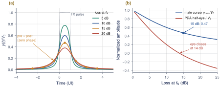
Take a cable with 15 dB of loss at \(f_\mathrm{N}=2.5\,\mathrm{GHz}\). Then \(k_dl=15/(8.686\times2.5\,\mathrm{GHz})=691\,\mathrm{ps}\), and \(\pi T_\mathrm{b}/(k_dl)=\pi\cdot200/691=0.909\). Equation (5.4) gives \(y_{\max}=(2/\pi)\arctan(0.909)=(2/\pi)(0.738)=0.470\,V_0\), so the main cursor has fallen to less than half.
The neighbours follow from Equation (5.3) at \(t=T_\mathrm{b}/2+kT_\mathrm{b}\): \(y_{\pm1}=0.153\), \(y_{\pm2}=0.043\) and \(y_{\pm3}=0.019\), in units of \(V_0\). Summing all cursors out to \(\pm100\) UI gives \(\sum\lvert y_k\rvert=0.527>0.470\), so the PDA eye is closed. Figure 5.2(b) shows that the eye of this model closes at about 14 dB.
A zero-forcing inverse needs \(+15\) dB at \(f_\mathrm{N}\). By Equation (5.1) with \(\lvert C\rvert^{-2}=e^{2af}\), its noise enhancement is \((e^{2af_\mathrm{N}}-1)/(2af_\mathrm{N})=\) 9.5 dB up to \(f_\mathrm{N}\). Up to \(2f_\mathrm{N}\) it would be 21.6 dB.
A zero-phase model is not a real channel
\(C(f)=e^{-k_dl\lvert f\rvert}\) is real and even, so its impulse response starts before \(t=0\) and is not causal. That is why its pre- and post-cursors are equal in Figure 5.2. A real channel such as REF is causal, and its post-cursors dominate (\(p_{1}=0.182\) against \(p_{-1}=0.049\)). Use the cable model for intuition about loss and the main cursor, and use REF (Section 3.7) for design numbers.
What this means for your design
Every 5 dB of loss at \(f_\mathrm{N}\) costs a large share of the main cursor and adds tail ISI. Near 15 dB the tails, not the main cursor, are what close the eye.
Equalize to about \(f_\mathrm{N}\) and no further. A full inverse to \(2f_\mathrm{N}\) roughly doubles the noise penalty in dB (12.1 dB becomes 22.5 dB on REF) and buys almost no eye.
Zero forcing ignores noise and swing. Every practical equalizer in this part of the book is a constrained version of it.
5.3Where equalizers live
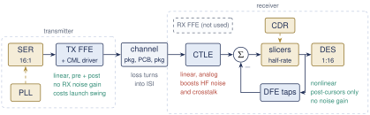
An equalizer can be placed at the transmitter, at the receiver input, or after the receiver’s decision. Figure 5.3 places the options in the Open-SERDES link, and Table 5.1 compares them.
TX FFE
A FIR filter in the driver pre-distorts the waveform (Chapter 6). It handles pre- and post-cursors and cannot amplify receiver noise, but with a fixed peak swing it can only lower the low-frequency level, so the eye arrives smaller.
RX CTLE
An analog high-pass stage at the receiver input (Chapter 7). It is cheap, fast and adaptable, and reshapes the long tail and part of the pre-cursor, but it boosts high-frequency noise and crosstalk with the signal.
RX FFE
A receiver FIR, from analog delay cells or after an ADC. It amplifies noise like a CTLE, and needs accurate 200 ps analog delays or a power-hungry ADC. Open-SERDES does not use it.
DFE
Subtracts the ISI that already-decided bits will cause (Chapter 8). Its feedback is a clean \(\pm1\) decision, so it adds no noise, but it cancels only post-cursors and its first tap must close a loop within one UI.
Figure 5.4 reads the REF pulse in these terms. Each zone of cursors has a natural owner.
| Cursors it fixes | Frequency view | Noise, crosstalk | Power | Main limit | |
|---|---|---|---|---|---|
| TX FFE | pre + post (as many as taps) | lowers LF, Nyquist kept | no RX noise gain; launch swing lost | low | peak swing; not adaptive without a back-channel |
| RX CTLE | long tail, some pre-cursor | boosts HF over LF | amplifies HF noise and crosstalk | low | peaking range and linearity |
| RX FFE | pre + post | like a CTLE, discrete taps | amplifies noise | high | analog delays or ADC power |
| DFE | post only (one per tap) | nonlinear (no \(H(f)\)) | no noise gain | medium | tap-1 timing, error propagation |
5.4Preview: who does how much?
None of the four is free: the TX FFE costs swing, the CTLE noise and linearity, the DFE timing margin and loop power. The design question is how to split the work of undoing 17.4 dB between them. Chapters 6–8 build each equalizer, and Section 8.5 answers the split with numbers for REF and for 5–30 dB channels.
Design rule of thumb
Give each equalizer the job it does most cheaply. The TX pre-tap takes the pre-cursor, the DFE takes the first one or two post-cursors without adding noise, and a linear equalizer (CTLE or TX post-tap) flattens the long tail. Any equalizer pushed far beyond its natural job costs more than it returns.
Key takeaways
Loss at \(f_\mathrm{N}\) spreads each bit into its neighbours. On REF the ISI sum exceeds the main cursor, so the PDA eye is \(-0.161\) V.
Equalization aims for a cascade that is flat up to \(f_\mathrm{N}\). In the time domain that means zero ISI cursors.
A zero-forcing inverse multiplies the noise by \(\int\lvert H_\mathrm{eq}\rvert^2\). That is 12.1 dB on REF up to \(f_\mathrm{N}\) and 22.5 dB up to \(2f_\mathrm{N}\).
In the zero-phase cable model, \(y_{\max}=(2V_0/\pi)\arctan(\pi T_\mathrm{b}/k_dl)\). At 15 dB of loss the main cursor is 0.47 and the eye is already closed.
The TX FFE, CTLE, RX FFE and DFE differ in which cursors they fix, whether they amplify noise, and what limits them.
The partition between them is a design decision. Section 8.5 makes it for Open-SERDES.
Generated from book/tutorial/chapters/05_eqfund.tex. Figure, table and equation numbers match the PDF edition.